Home Officers Trails Upcoming Events Recent Events Links Join


Wood's Covered Bridge at Bridgeport
Herb Lindberg
Updated February 5, 2022

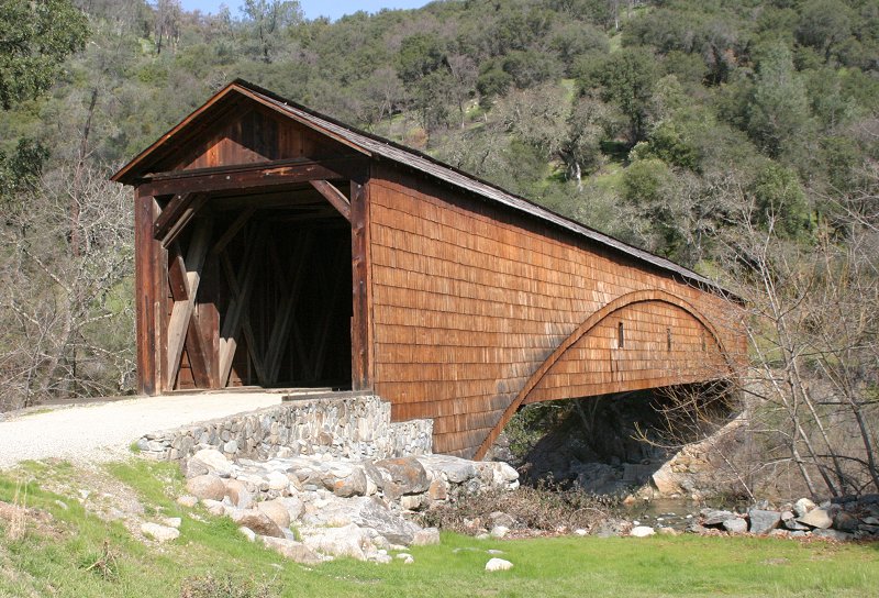
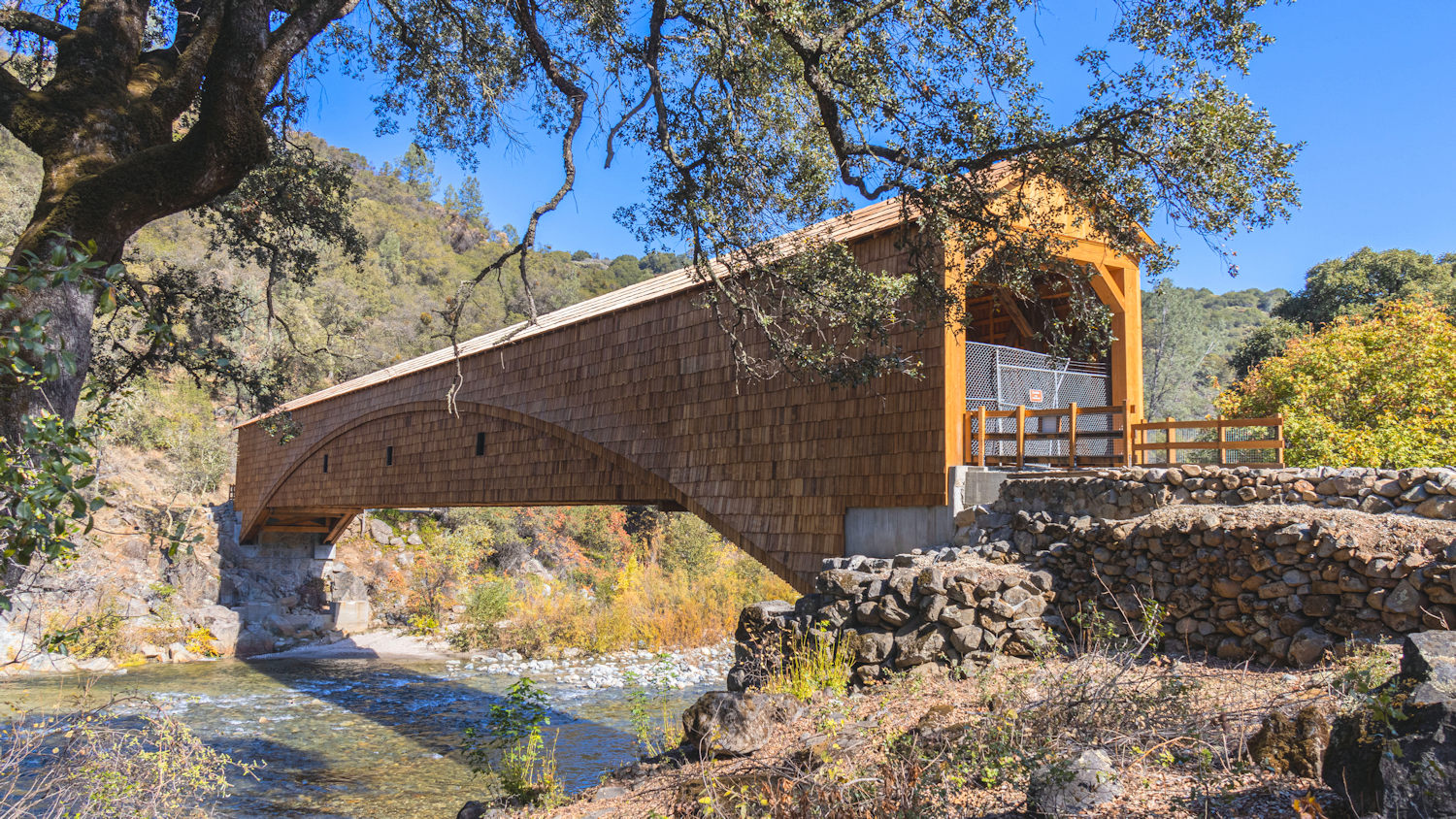
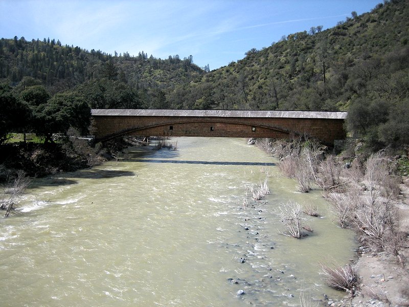
The present wooden bridge at Bridgeport was built in 1862 by David I. Wood, to replace his 1850 bridge which washed away in a 
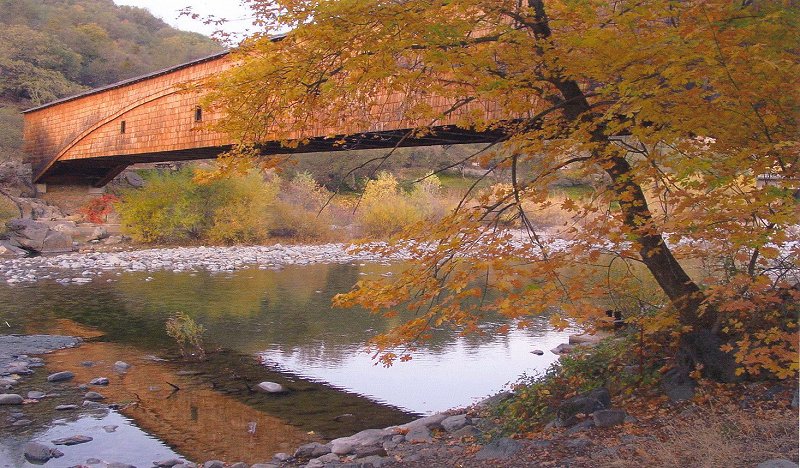
storm.  At 229 feet (251 feet before the end walls were removed) it is thought to be the longest single-span covered bridge in the United 
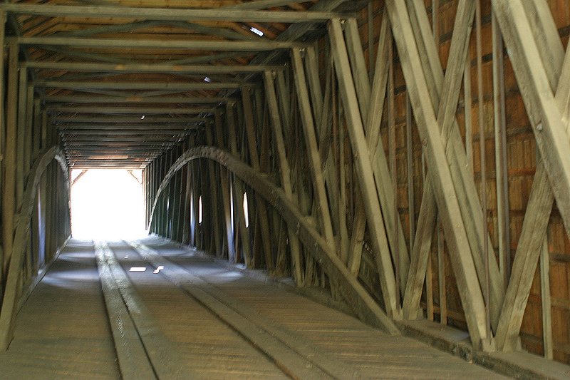
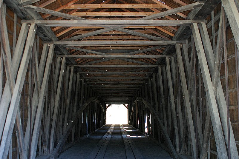
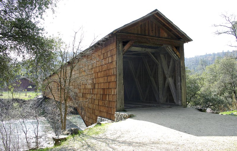
States and perhaps the world.  As with all such bridges, the cover serves mainly to keep the rain off the load-bearing structure, which would otherwise soon rot from the moisture.

The bridge was heavily damaged in 1997 by flood-stage flow of the river, which lapped at the bottom of the bridge and threw huge floating logs against the bridge until it was splintered and near collapse.  This damage was soon repaired after heavy lobbying for funds by the community.  Then in 2010 the bridge  showed signs of severe rotting of the west top chord and near an abutment. By 2011 the damage was so severe that the bridge was closed even to foot traffic.

Dave Anderson, then President of the South Yuba River Park Association (SYRPA), decided to bring Bridge supporters together around his dining room table in early 2013 to take action. They formed the Save Our Bridge Campaign Committee chaired by Doug Moon, which led to another outpouring of community support and resulted in initial funding for the restoration. The 
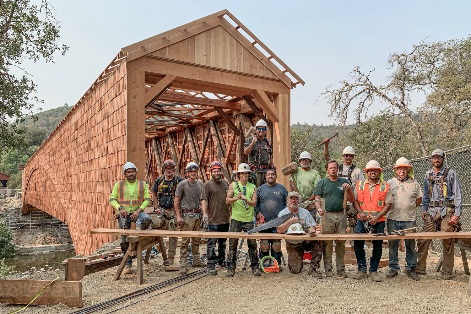
project took place in two stages: 1) Stabilization, which was achieved at a cost of $268,000 and 2) Restoration, with $1.3M in State and Federal funding. The total cost of the Restoration phase of the project would rise to over $6M when the final construction was completed in 2021.

A groundbreaking ceremony was held on September 2, 2014 to thank the many people responsible for obtaining the funding and to celebrate the immediate start of Stabilization Construction. Short video of construction. After years more of community-wide support and lobbying, $6M+ of Restoration Construction began in June, 2019.

Restoration was completed in August, 2021 and is summarazed in a 43-minute video prepared for an opening celebration held at the park on November 4, 2021. Restoration of the Covered Bridge at Bridgeport, CA - Full

Comments on the video:
"This is a stunning account of an epic project. Beautifully done!"  Courtney Ferguson, freelance columnist for The Union.
"Absolutely amazing video. Thanks to you and the photography team."  Ron Ernst, former President of SYRPA.

The 
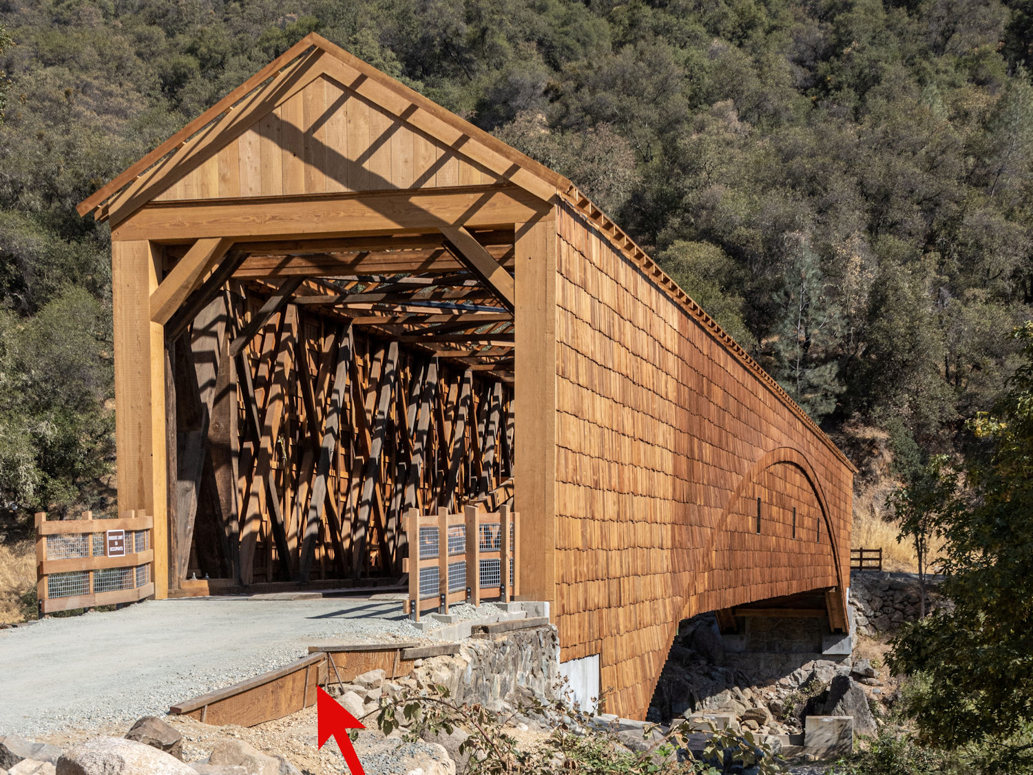
bridge was formally reopened in a grand celebration at the bridge on November 4, 2021. The celebration and school children's participation in it are described in a 5-video playlist.  The last two videos are the restoration video above and installation of the roof with beautiful arial views of the completed bridge.

Bridge Rehabilitation Material Re-Use Data (Docents take note)
o Wrought Iron nails in chords: 400 straightened and re-used, plus many never removed from bottom chord.
o Wrought Iron truss rods: 7.4% re-used
o Main- and counter-brace timbers: 61% re-used
o All of the roof and sidewall framing and shakes are new wood, save for the six window frames looking out on the river.

General covered bridge restoration reference, recommended by Master Bridgewright Tim Andrews, with Bridgewright Will Truax:
GUIDELINES FOR REHABILITATING HISTORIC COVERED BRIDGES, edited by Christopher H. Marston and Thomas A. Vitanza, Published in 2019 by the Historic American Engineering Record, National Park Service, Washington, DC., Library of Congress Control Number: 2018911948
ISBN: 978-0-692-17092-2.

Another interesting text on early bridge designs is Covered Bridges and the Birth of American Engineering by multiple authors and several editors, including Christopher H. Marston.

Visitors enjoy a ride across the bridge during Spring Festival, April 29, 2007.
This was Cal Rowlands' last year driving his horses and classic wagon at our celebrations.


Classic view, from Park Headquarters end.
(Photo also provided to California State Parks for their brochure on the park.)


Bridge sans roof just after being rehabilitated, August, 2021, North Portal view,
along with most of the bridgewrights, timber framers and carpenters.
Near center are bridgewright Will Truax (kneeling) and master bridgewright Tim Andrews.
Photo by John Field, Producer of photo and video coverage of entire rehabilitation process.

South Portal with safety railings installed, also sans roof, Photo by John Field

Completed with roof on October 29, 2021, west side view, Photo by John Field


Back to old pre-rehabilitation photos

Bridge in evening with fall color
(photo courtesy of Betty Kelly)

.
As you see here, the bridge is supported by a cross-brace truss with metal tie rods (Howe Truss) and also an arch.  This is called a Burr Arch Truss.  In addition to adding overall strength the truss prevents buckling of the arch as heavy loads enter and leave the bridge.  See Technical Discussion of trusses below.*

Another view of the Burr Arch Truss.
The new wood of the roof truss is part of the re-construction done after a severe storm in 1997.


The exceptionally long span is apparent in this side
view from the modern Pleasant Valley Road bridge.


A less familiar picture from the opposite end, with The Barn in the background


*Technical Discussion

You can recognize this as a Howe truss because in the main span the stronger diagonals (done with doubled timbers in this case) tilt toward the center of the bridge, which makes them compression members.  The vertical members are tension tie rods.  If the stronger diagonals tilt away from the center of the bridge, they are in tension (Pratt Truss) and the vertical members must be compression posts.  The Howe truss was favored in the Gold Rush era because it uses less wrought iron and more wood, which was available locally.  The steel bridge at Purdon Crossing (1895) uses a Pratt Truss.

The above conclusions are explained by  considering sketches of the bare essentials of the two truss designs.

The rectangle in Sketch A represents an undeformed truss element sans cross member, taken from the right side of either truss.  Sketch B shows the same element in a deformed state as it is sheared by the downward load and upward reaction from the bridge abutment.  One diagonal becomes shorter (in blue) and hence is in compression, while the other becomes longer (in red) and hence is in tension.  In the Howe Truss, Sketch C, the diagonals are in the compression direction, and in the Pratt Truss, Sketch D, the diagonals are in the tension direction.  Either truss must carry the bending load, which is done by the upper truss members (upper chords) going into compression and the lower members (lower chords) going into tension, as indicated by the colors. The truss structure keeps the chords separated as well as carrying the shear forces induced at the abutments.

(In Wood's bridge both upper and lower chords in the main span are made of 8 thinner layers to avoid shear cracks along imperfections, which would be unavoidable in a single piece of thick wood. To keep the thin layers from shearing (sliding on each other) or buckling (in the upper chord under compression), they are stitched together with heavy wrought-iron bolts. In today's technology such laminations are held together with glue and called glulams.)

Now direct your attention to the internal vertical members of the trusses, in particular the ones extracted in the right-side sketches.  In the Howe truss, the diagonals are in compression and are pushing outward on the ends of the vertical member, which is therefore in tension.  In the Pratt truss, the diagonals are pulling inward on the ends of the vertical member, which is therefore in compression.  These members can therefore be simple tie rods in the Howe truss but must be buckle-resistent posts in the Pratt truss (see Lindberg page 9 for a very technical discussion of buckling).

We are now in a position to look more closely at Wood's bridge to see that it indeed uses a Howe truss design. In the picture below you can see that the doubled, and much larger, timbers tilt toward the center of the bridge.  You can also see the steel vertical tie rods that extend from the top of one doubled cross member to the bottom of the next.

Close view near the end of the bridge (off on right).


Crop into above picture to show the lower end connection of the tie rods.


The Burr Arch and Truss was designed such that either the arch or the truss could carry the design load by itself, when the load is uniform or near the center of the bridge.  When the load is near the ends of the bridge (a heavily loaded wagon and horses), however, an arch alone tends to buckle under combined compression and local concentrated load.  The added Howe truss carries local loads very well because it is uniformly strong on the scale of the brace triangles.  Note also that the first cross brace at either end of Wood's bridge has thick members in both tilt directions, again to carry local loads near the ends of the bridge which would otherwise tend to buckle the arch.

A Bit of Howe Bridge History

Part of William Howe's 1846 Patent Application


From Will Truax, Bridgewright working on current bridge rehabilitation: "William Howe’s 1846 patent drawings hold detailing uncommon to the Howe bridge that are/were found at Bridgeport. Note the brace which descends from the top chord and joins the arches at the springstone / abutment - A version of that was present in the Bridgeport bridge until the botched 70’s rehab."

Home