|
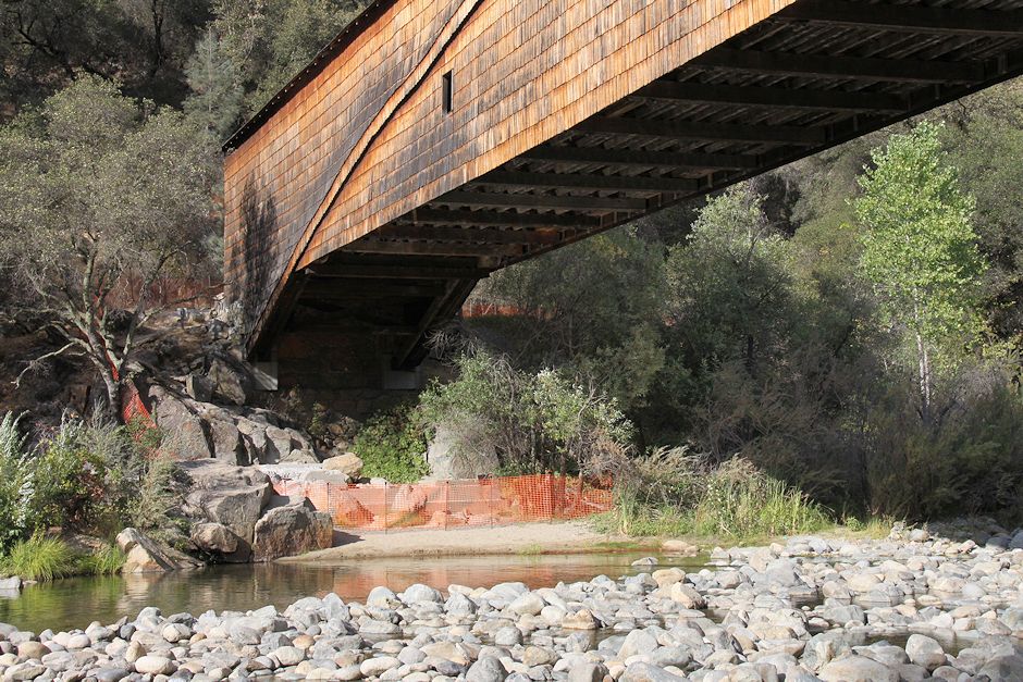
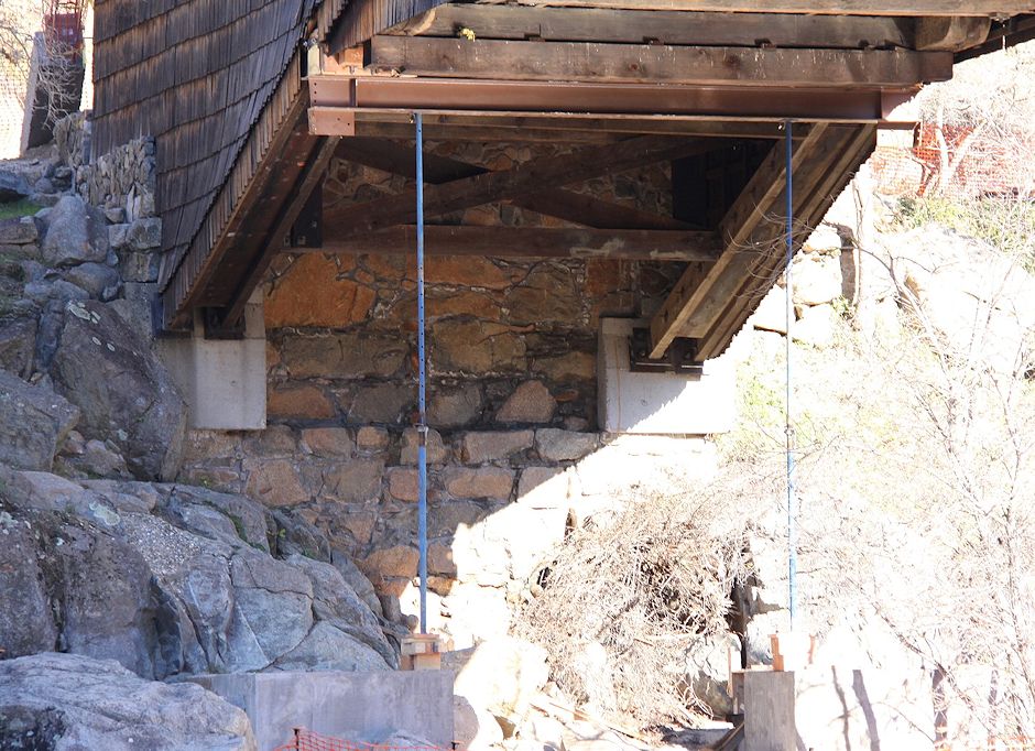
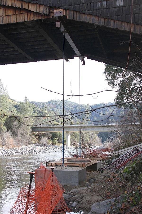
Underside of the
south end of the bridge (Visitor Center end) just before beginning
cradle construction in earnest. |
 |
|
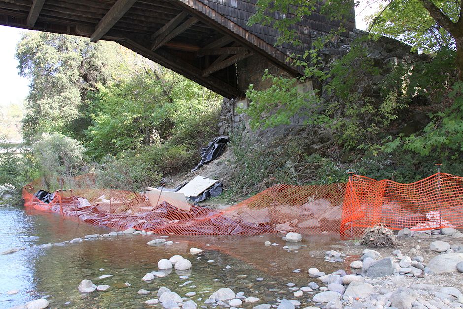
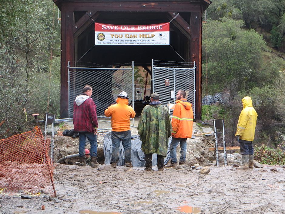
Phase
1 to Save the Covered Bridge When final reconstruction of the bridge is complete, almost
all traces of the temporary cradle will have been removed. The photos
on this and an accompanying page, taken by John Field and Shirley Moon,
will be the primary record of this important step in saving the covered
bridge at Bridgeport. Short video of same material. |
|
Underside of the
south end of the bridge (Visitor Center end) just before beginning
cradle construction in earnest. |
|
|
Underside of the north
end. |
 |
|
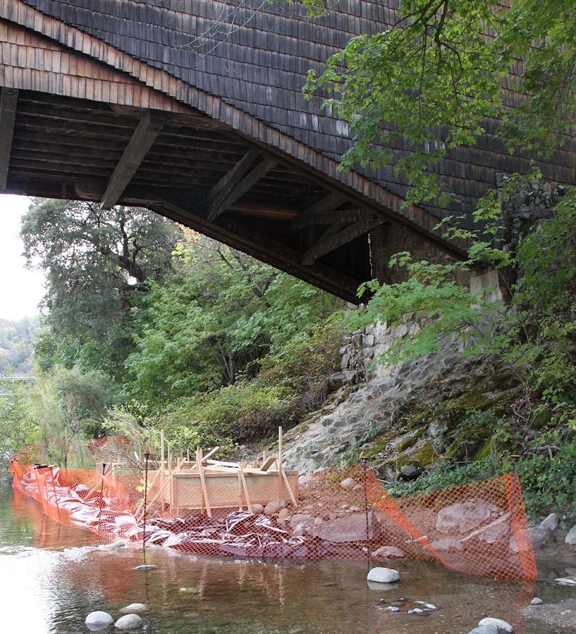
Forms for south-end
piers. |
 |
|
More global view of
bridge and south-end pier forms. |
 |
|
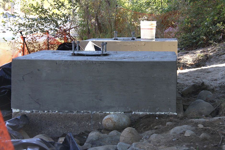
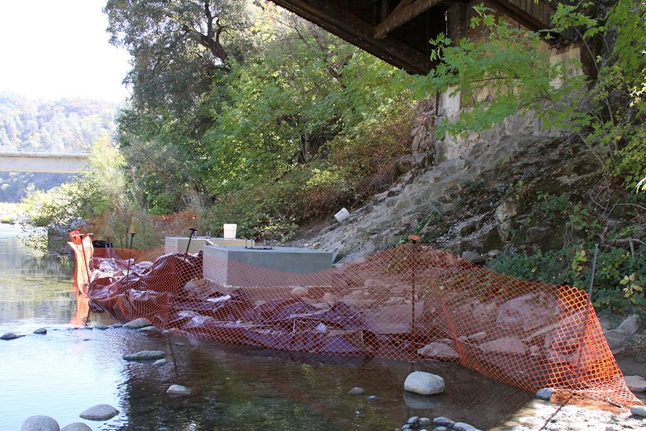
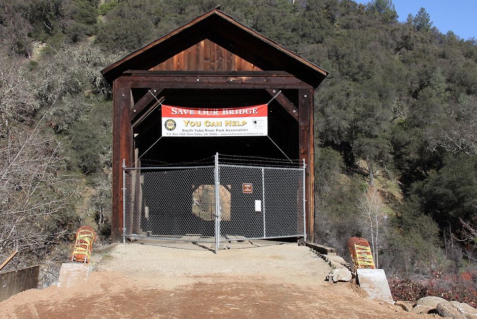
Concrete piers after
forms were removed. |
 |
|
Modern bridge in
background confirms this is the south end of the bridge. |
 |
|
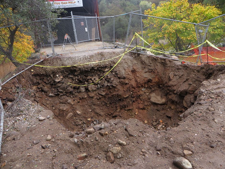
Enormous hole dug at
south end for high-strength steel rod anchors. |
 |
|
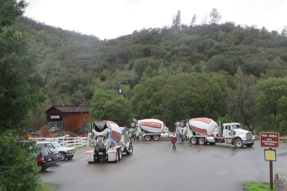
Three trucks full of concrete to fill the hole. |
 |
|
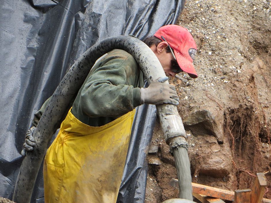
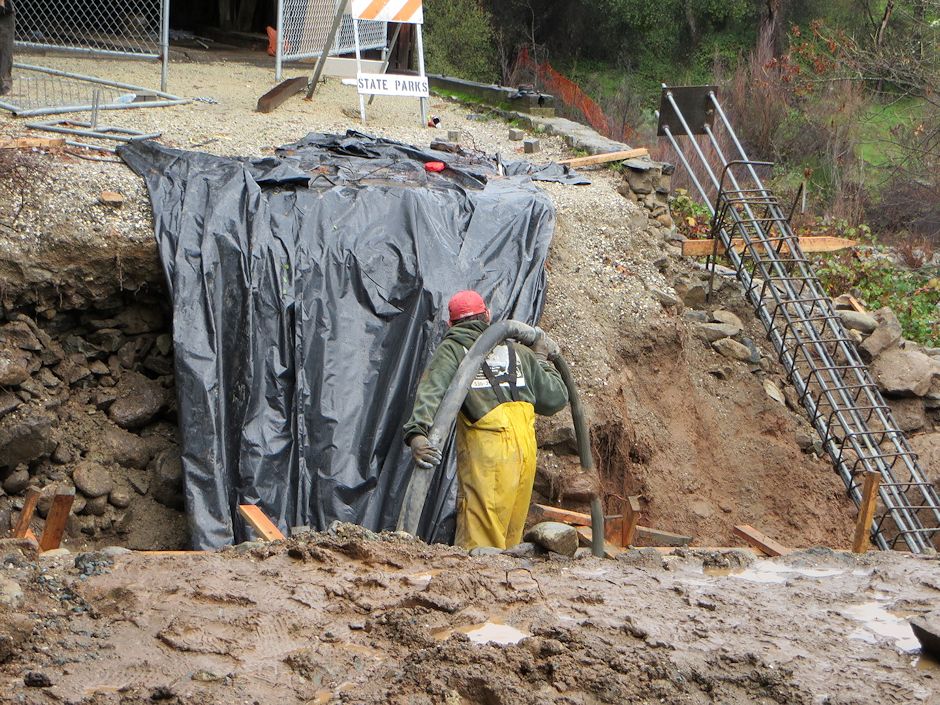
Begin pumping concrete
into the hole. |
 |
|
Continue pumping. Note the rebar cage for one of the steel rod
anchors,
which will be included in the pour. |
 |
|
Still pouring. Note the anchor rebar cages aligned with
each side of the bridge. |
 |
|
Concrete pour is
complete and partly cured.
Note that the cable anchor cages had concrete forms added during the
pour. |
 |
|
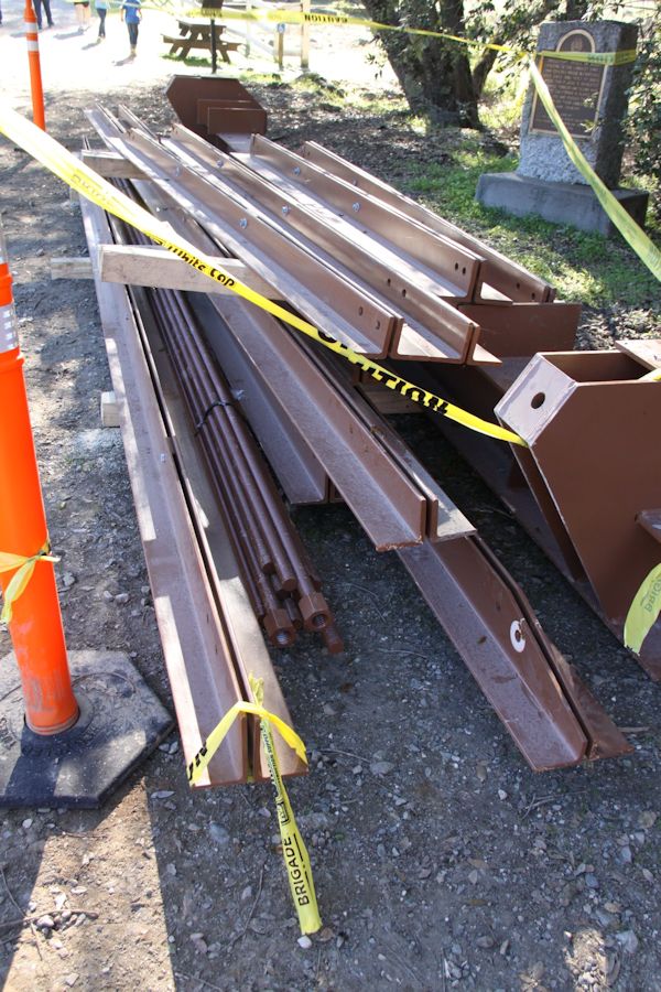
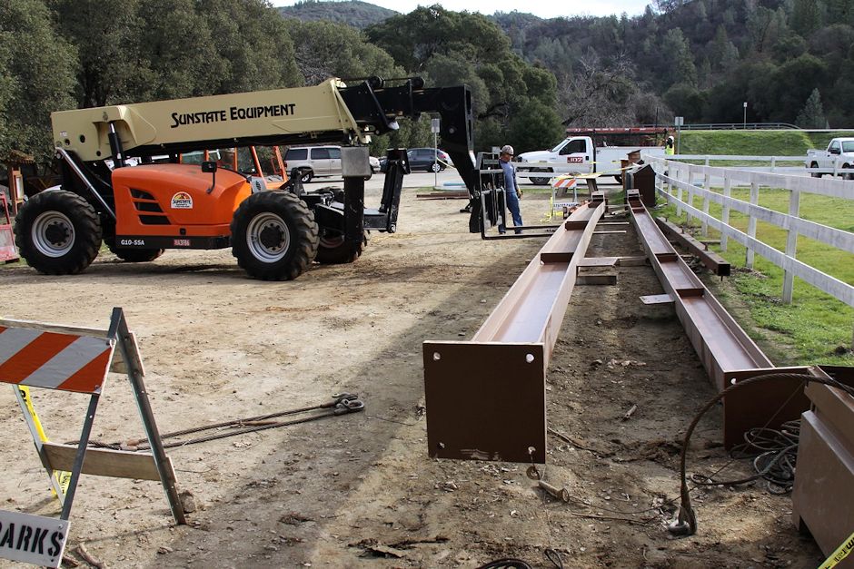
Stack of ASTM A36
(36-ksi strength) steel
pre-cut members to create the cradle. |
 |
|
One of the four cradle
cross beams in place above the north-end piers. |
 |
|
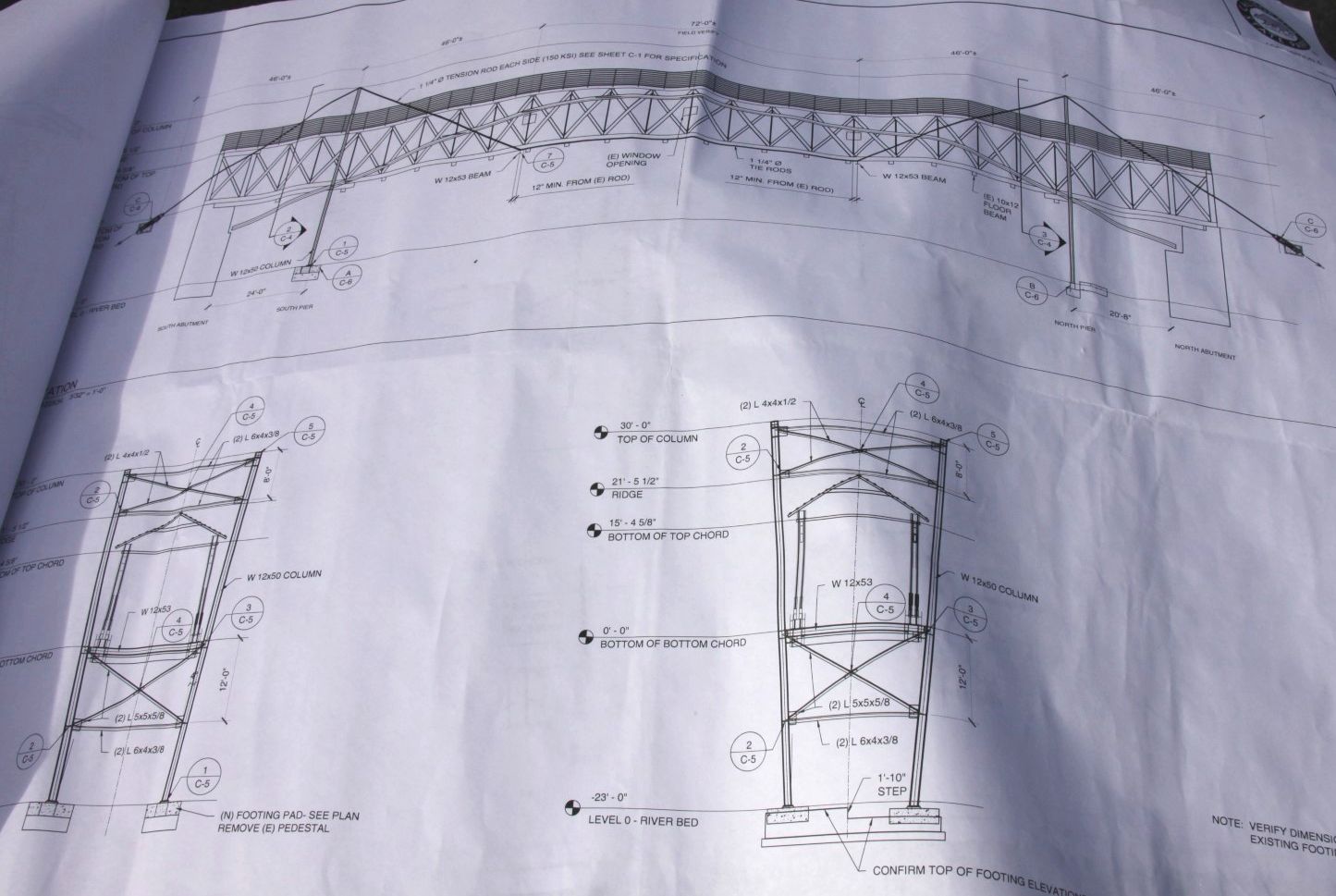
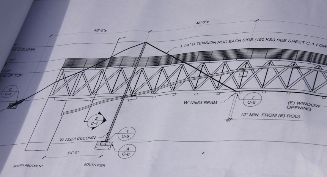
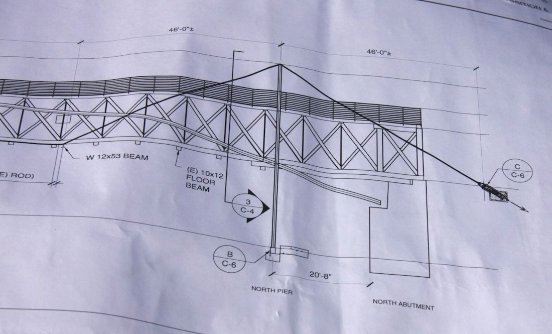
Construction drawing
for the cradle. The end views
show the bridge cross section cradled between columns on each
side. Four cross beams at the base of the bridge will carry the
bridge. |
 |
|
 |
|
Mirror image
construction at the north end of the bridge. |
 |
|
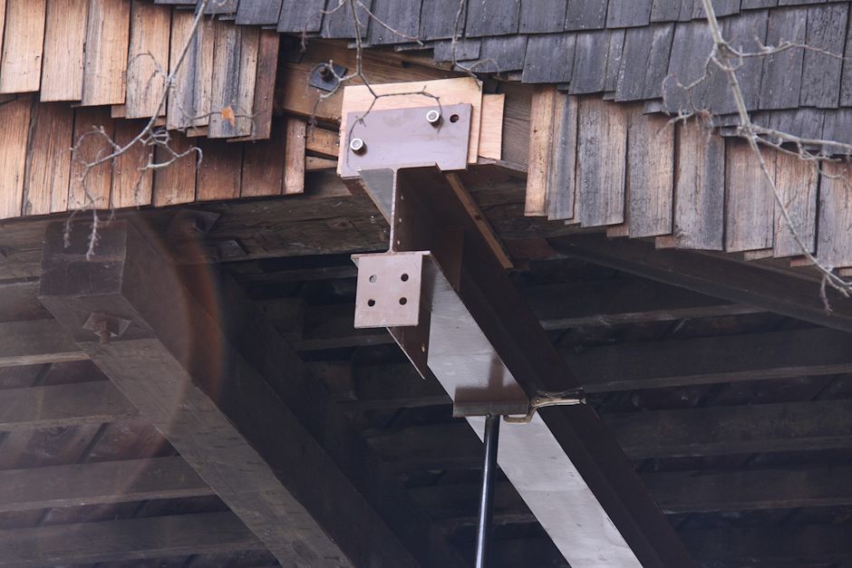
Cross beam and its
temporary support from the south piers. |
 |
|
Close-up of the south
cross beam and its connection plate to be bolted to the southwest column. |
 |
|
Two of the four columns
ready for pre-assembly into a column pair. |
 |